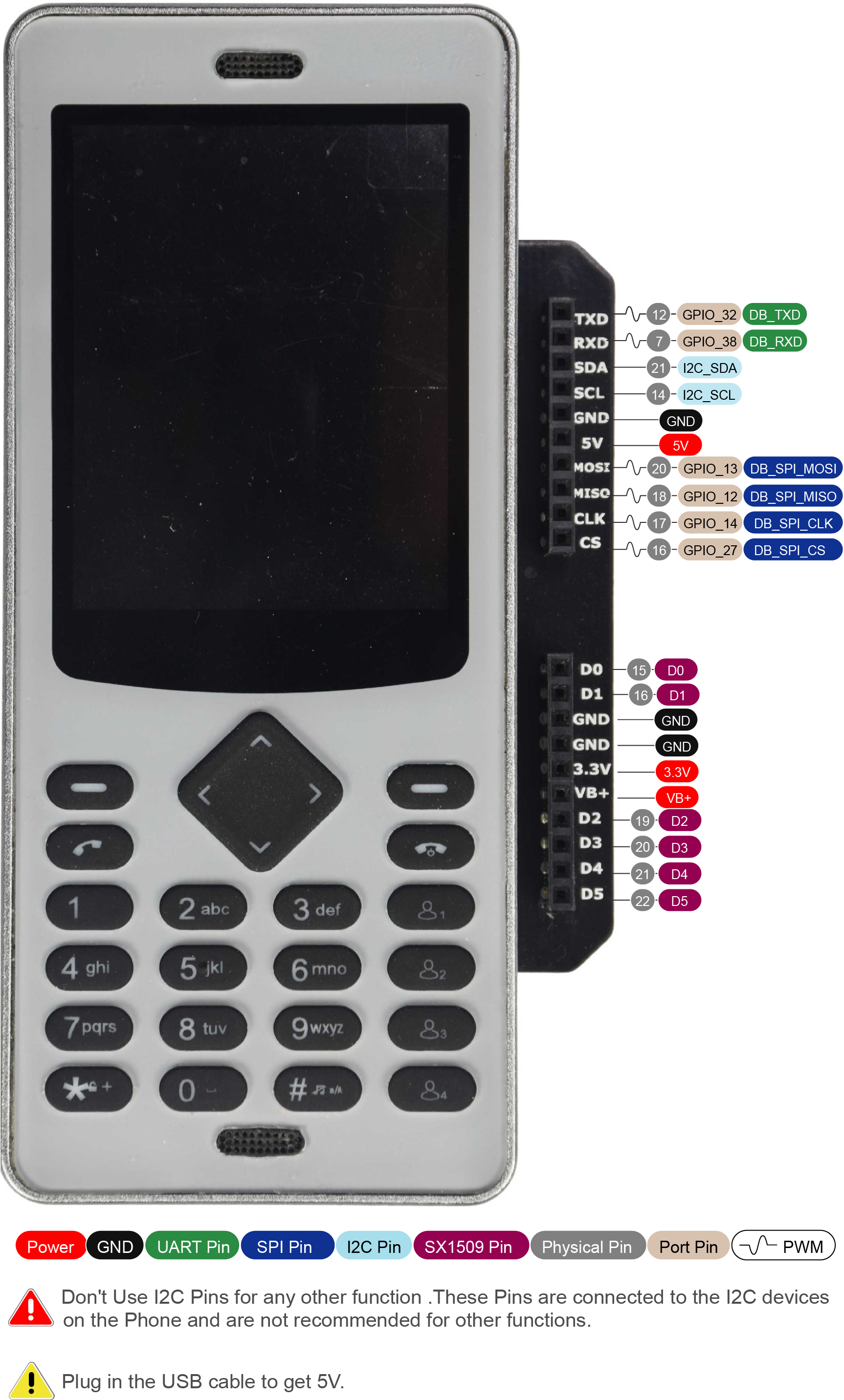
Description
0.1" Header breakout daughterboard is intended to help desktop and breadboard prototyping by breaking the pins on the back of the WiPhone out to forward facing 0.1" (2.54mm) headers.
Features
- Female Header access to WiPhone and SX1509 GPIOs.
- Female Header access to WiPhone battery.
- Female Header access to 5V power from USB connector.
- Female Header access to 3.3V power from WiPhone.
Technical Details
0.100" (2.54 mm) Female Header: 1x10-Pin, Straight
- Current rating: 3.0 AMP
- Contact resistance: 20mΩ Max
- Insulation resistance: 1000MΩ Min
- Withstanding Voltage: AC/DC 500V
- Contact material: Brass/Gold plated.
- Operation temperature -55°C to +105°C
- Compliant with RoHS
The more general dimension diagram for an XX-pin version of this Female Header is shown below.
.png)
Peripherals and GPIO
| Peripheral Type | Qty | Input(I) / Output(O) |
|---|---|---|
| Digital | 11 | I/O |
| Digital | 1 | I |
| Analog (ADC) | 5 | I |
| UART | 1 | I/O |
| SPI | 1 | I/O |
| I2C | 1 | I/O |
| USB-UART | 1 | I/O |
| PWM | 11 | O |
Pinout

| Pin | Arduino Pin | Description |
|---|---|---|
| 5V | This pin is internally connected to the VBUS of USB port. | |
| VBAT | This pin is internally connected to the positive terminal of the LiPo battery connector. | |
| 3.3V | This pin is connected to the dedicated on board voltage regulator for daughter board. | |
| GND | This pin is connected to System GND. | |
| DB_RXD | 38 | Connected to Mainboard RX.Can be used as DIGITAL INPUT PIN(GPI_38) |
| DB_TXD | 32 | Connected to Mainboard TX.Can be used as DIGITAL PIN(GPIO_32), ANALOG PIN (ADC1_CH4) and PWM PIN |
| DB_SPI_MISO | 12 | MISO for Daughter board SPI. Can be used as DIGITAL PIN(GPIO_12) ANALOG PIN (ADC2_CH5) and PWM PIN. |
| DB_SPI_MOSI | 13 | MOSI for Daughter board SPI. Can be used as DIGITAL PIN(GPIO_13), ANALOG PIN (ADC2_CH4) and PWM PIN. |
| DB_SPI_CLK | 14 | Clock for Daughter board SPI. Can be used as DIGITAL PIN(GPIO_14), ANALOG PIN (ADC2_CH6) and PWM . |
| DB_SPI_CS | 27 | CS for Daughter board SPI. Can be used as DIGITAL PIN(GPIO_27), ANALOG PIN (ADC2_CH7) and PWM PIN. |
| I2C_SCL | 25 | Clock pin for I2C (GPIO_25).Not recommended for any other function. |
| I2C_SDA | 15 | Data pin for I2C(GPIO_15).Not recommended for any other function. |
| D0-D5 | EXTENDER_PIN(10) - EXTENDER_PIN(15) | These pins are generic IO pins connected to SX1509 IO expander |
Warning
Note
For more detailed information about each pin please check WiPhone Technical Manual